Saturday, October 14, 2006

Stainless Steel for Cookware and Kitchen Applications

Background

Stainless Steel has long been the first choice of designers, manufacturers and users of cookware through its unique combination of properties that provide highly attractive benefits. For pots and pans optimum heat transfer is achieved using a bonded Aluminium or Copper base. In the best quality items this base has a ‘sandwich’ construction with the Aluminium or Copper being completely enclosed with Stainless Steel inside and outside.

Advantages for Stainless Steel for Cookware

Both the professional and amateur user value the fact that stainless products do not stain, chip or rust, are robust and do not affect the flavour of the food, plus they are easy to clean and dishwasher safe. Volume production ensures that high quality finished goods, which with appropriate care can last a life-time, are available at competitive prices. What’s more, being fully recyclable, stainless steel has good environmental credentials, with most producers making new stainless using a high proportion of recycled scrap.

Why Manufacturers Like to Use Stainless Steel for Cookware

Manufacturers welcome designs in stainless steel as the material is readily formable and weldable as well as being easy to finish with a range of attractive finishes. They also like the high quality image that stainless steel tends to provide for their products.

All this means that designers enjoy working in stainless knowing that their products will be easy to make, popular amongst buyers and long lasting.

The Increasing Use of Stainless Steel for Kitchen Applications

The popularity of stainless steel in the kitchen, promoted by campaigns throughout the world, such as ‘Stainless Steel Appeal’ (www.stainlessappeal.com) in the UK, continues to drive growth in world consumption upwards by over 5% per annum. The last ten years has seen more and more stainless steel appearing in kitchen items from toasters to kettles, ovens to microwaves, dishwashers to washing machines and fridge doors to kitchen cupboards.

Case Study - Camerons Cookware

So when designers come to develop new cookware products it is hardly surprising they think of stainless first. Some products recently introduced to the UK highlight how stainless steel aids innovative cookware design. All designed by Chris and Anne Malone of Colorado Springs, USA these products stem from a lifetime interest in cookware and good food.

Cookware Designer Chris Malone said “We developed the Camerons Stovetop Smoker to bring exciting and healthy new flavours to the home stovetop. The BeerRoaster is our solution to dry, flavourless roast chicken whilst the Multi-Roaster filled an obvious gap in what was available on the market. I never considered any material other than stainless steel for its excellent combination of properties, the freedom it gives the designer and the ease of manufacture of the products. These new products have proved very popular in the USA and I hope that UK cooks, chefs and gourmets get as much enjoyment from them.

AZoM - Metals, Ceramics, Polymer and Composites : Stainless Steel for Cookware and Kitchen Applications – Camerons Stovetop Smoker

Camerons® Stovetop Smoker® allows you to smoke foods of all types on your own stove.

Smoke-cooking is a healthy way to infuse flavour without the use of fats, salts or oils and that means no added calories either.

Hot-smoking food retains moisture and natural cooking flavours so foods don't dry out or get tough

Smoker also doubles as a steamer, so you really get two great cookers in one product

Works well with all meat, seafood, and poultry dishes and it transforms ordinary vegetables into delicious main courses

AZoM - Metals, Ceramics, Polymer and Composites : Stainless Steel for Cookware and Kitchen Applications – Camerons® Chicken Beer-Roaster

Camerons® Chicken Beer-Roaster® allows you to enjoy a full size fresh broasted chicken indoors or outdoors on your barbeque using your favourite beer, marinade or fruit juice to enhance the flavour. The vertical design allows reduced fat while maintaining the moisture.

AZoM - Metals, Ceramics, Polymer and Composites : Stainless Steel for Cookware and Kitchen Applications – Camerons® Multi-Roaster

Camerons® Multi-Roaster® is actually three top quality stainless steel cookware products combined to roast, sauté, casserole and bake your favourite foods

The oval 11.5 Litre Roaster, can hold a 20 lb (8.5 kg) Turkey, Large Chicken, or Medium to Large Roast

The Aluminium base insert for better heat transfer and no hot spots

The bottom can be used as a Sauté Pan or Stock Pot whilst the top can be used as a Sauté Pan, Open Casserole or Serving Tray

Stainless Steel Grade 302HQ

Background

302HQ is a specialised wire grade finding very wide usage for manufacture of stainless steel fasteners. The inclusion of 3% copper in the composition reduces the cold work hardening rate substantially compared to Grade 304. This grade is the standard material for manufacture of self-tapping screws and light machine screws and is also used for some bolts, set screws, rivets and specialised fasteners. 302HQ has now totally replaced Grades 384 and 305. Alternative designations for Grade 302HQ include "XM-7", "304Cu" and "304HQ". The stable austenitic structure makes 302HQ non-magnetic, even after substantial cold work, and also results in excellent toughness, even down to cryogenic temperatures.

Key Properties

These properties are specified for wire in ASTM A493; wire is the only commonly available form for this grade.

Composition

Typical compositional ranges for grade 302HQ stainless steels are given in table 1.

Table 1. Composition ranges for 302HQ grade stainless steel

Grade

C

Mn

Si

P

S

Cr

Mo

Ni

Cu

302HQ

min.

max.

-

0.03

-

2.00

-

1.00

-

0.045

-

0.030

17.0

19.0

-

8.0

10.0

3.0

4.0


Mechanical Properties

Typical mechanical properties for grade 302HQ stainless steels are given in table 2.

Table 2. Mechanical properties of 302HQ grade stainless steel

Grade

Tensile Strength (MPa) max.

Yield Strength 0.2% Proof (MPa)

Elongation (% in 50mm)

Hardness

Rockwell B (HR B)

Brinell (HB)

302HQ annealed

605

-

-

-

-

302HQ lightly drawn

660

-

-

-

-

Above values from ASTM A493. Higher strengths can be produced by heavy cold work - this may be required for certain applications.

Physical Properties

Typical physical properties for annealed grade 302HQ stainless steels are given in table 3.

Table 3. Physical properties of 302HQ grade stainless steel in the annealed condition

Grade

Density (kg/m3)

Elastic Modulus (GPa)

Mean Coefficient of Thermal Expansion (mm/m/°C)

Thermal Conductivity (W/m.K)

Specific Heat 0-100°C (J/kg.K)

Electrical Resistivity (nW.m)

0-100°C

0-315°C

0-538°C

at 100°C

at 500°C

302HQ

8027

193

17.2

17.8

18.8

16.3

21.5

500

720

Grade Specification Comparison

Approximate grade comparisons for 302HQ stainless steels are given in table 4.

Table 4. Grade specifications for 302HQ grade stainless steel

Grade

UNS No

Old British

Euronorm

Swedish SS

Japanese JIS

BS

En

No

Name

302HQ

S30430

394S17

-

1.4567

X3CrNiCu18-9-4

-

SUS XM7

These comparisons are approximate only. The list is intended as a comparison of functionally similar materials not as a schedule of contractual equivalents. If exact equivalents are needed original specifications must be consulted.

Possible Alternative Grades

Possible alternative grades to grade 302HQ stainless steels are given in table 5.

Table 5. Possible alternative grades to 302HQ grade stainless steel

Grade

Why it might be chosen instead of 302HQ

304L

A higher work hardening rate can be tolerated - or is needed.

316L

Higher resistance to pitting and crevice corrosion is required in chloride environments; the higher work hardening rate of 316L is acceptable.

430

A lower cost is required, and the reduced corrosion resistance of 430 is acceptable.

Corrosion Resistance

Excellent. Equal to or exceeding that of Grade 304 in a wide variety of corrosive media. Subject to pitting and crevice corrosion in warm chloride environments, and to stress corrosion cracking above about 60°C. Considered resistant to potable water with up to about 200mg/L chlorides at ambient temperatures, reducing to about 150mg/L at 60°C.

Heat Resistance

Good oxidation resistance in intermittent service to 870°C and in continuous service to 925°C. Continuous use of Grade 302HQ in 425-860°C range is usually safe (free of carbide precipitation) as the grade has a very low carbon content.

Heat Treatment

Solution Treatment (Annealing) - Heat to 1010-1120°C and cool rapidly. This grade cannot be hardened by thermal treatment.

Welding

Use Grade 308L rods or electrodes. Excellent weldability by all standard fusion methods, both with and without filler metals. Because of its applications this grade is not often welded. Exceptions are resistance butt welding to join wires together during wire manufacture, and when the grade is used to make stud welding fasteners. 302HQ is not specifically listed in AS 1554.6.

Machining

302HQ is rarely machined, because of its form and likely products. The grade always has very low sulphur content as this aids formability, but unfortunately this also reduces machinability. Machining is certainly possible.

An Improved Machinability version of Grade 302HQ is produced, having a very high machinability. This version has a slightly higher sulphur content and is also calcium treated. This Improved Machinability grade (referred to as Ugima 4567) is available only to special order.

Cold Work Hardening

302HQ has the lowest work hardening rate of any of the common austenitic stainless steels. This results in a tensile strength increase of approximately 8MPa/%Ra (8MPa increase in tensile strength for each 1% reduction of area of cold work - this data from wire drawing). Even after substantial cold work this grade remains essentially non-responsive to a magnet.

Applications

Typical applications include:

· All severe cold heading applications

· Self-tapping screws

· Roofing bolts

· Machine screws

· Bolts

· Set screws

· Blind rivets

Thursday, October 12, 2006

Solid State Joining Techniques

Background

For some materials and material combinations the use of fusion welding is not practicable. Intermetallics may be formed at the joint interface or cracking may occur at or near the interface, which restricts the use of the joint in any service application where significant loading has to be withstood. However, while resistance welding, friction welding and their derivatives have been around for many years, the range of solid state joining techniques that are available may not be widely known in the fabrication and construction industry. The advantages of these technologies, apart from the avoidance of problems from molten and solidified material, are that the processing times can be very short and with minimal heat input, so they can also be attractive techniques for joining materials that are weldable by standard processes.

The Process

The key aspect of a solid state joining process is that, after the application of heat to soften the materials, a force is applied to squeeze out the softened material, thereby dispelling any existing surface oxide films that may be present. Friction welding achieves the heating usually by rotary or linear oscillation to promote relative motion of one component against the other, while pressure is applied normal to the faces. When the motion ceases and the final forging pressure is applied, there will be some additional flash extruded from the joint region, which can usually be easily machined away.

Flash Removal from Internal Surfaces

In the case of rock drills, however, the internal flash created in the bore of the tube is not easily accessible for removal, but Thompson Friction Welding has devised a gas pulsing system with oxygen and nitrogen being blown alternately down the bore during processing, which removes the flash as it is formed and can leave a concave or convex inside profile if required, figure 1. Because the softened material is being extruded out of the joint line, allowing clean metal to adhere to clean metal, there are no contamination problems, despite using oxygen.

Figure 1. Rock drills formed by solid state joining showing the absence of welding flash.

Friction Welding Techniques

Radial Friction Welding

Stolt Comex Seaway is developing a radial friction welding technique for offshore pipelines and risers of 150-320mm diameter. This is effected by rotating a profiled ring between two static pieces of pipe and radially compressing the ring so that it welds onto both pipe sections simultaneously. It has been found that sound welds in the 13% super-martensitic steels, which an cheaper but less weldable by fusion welding than the super-duplex steels, can he made in about 15 seconds, and the ring allows the possibility of introducing a non-matching material in the joint properties require it.

Friction Stir Welding

The friction welding derivative that is currently being developed most widely for application in a variety of industries is friction stir welding developed by TWI in 1991. In this technique, non-consumable tool is rotated and traverse through the material to be joined, forming a platicised annulus around the central pin, whereby material is transferred from the front to the back of the pin, eliminating the joint interface. The main use at the moment is for aluminium alloys in the shipbuilding and aerospace industries. ESAB is a major friction stir welding machine builder for both industries, and has delivered three large industrial machines to Boeing in the USA during the period 1997-1999, figure 2. They are used to weld items such as the fuel tanks and assemblies used on the Delta series of rockets, which range in size from 3.6-18 m long and 2.4-4.2 m in diameter. The first fully friction stir welded component, a cylindrical intermediate assembly, was launched from Cape Canaveral on 17 August 1999. In parallel with the many current industrial applications with aluminium, friction stir welding is also being developed for joining copper, titanium and steels - in steels, welds have already been made in 25 mm thick material and transition joints between dissimilar steels have also been achieved.

Figure 2. The ESAB SuperStir friction welding machine for Delta 2 rocket components.

Linear Friction Welding

At the other end of the material spectrum, TWI has applied linear friction welding to joints in polyethylene pipes. In this case some of the material is melted and then squeezed out of the joint line. The main attraction of the process is that the welding time is only about one minute for 125 mm diameter pipe with a 12 mm wall thickness, whereas the more standard techniques of hot plate butt fusion and electrofusion can take up to 11-12 minutes. The process has already been developed for pipes up to 180 mm diameter and in other plastic materials, and has considerable further potential.

Electric Resistance Welding Techniques

Flash Butt Welding

Several techniques involve the use of the passage of electricity to soften the mating surfaces of the two components. Flash butt welding uses resistance heating with very high currents to provide the energy required for this softening, but the recent process improvements at the Paton Institute have concentrated on modifying advanced power supplies to create pulsed flash butt welding. With a greater energy efficiency it has been possible to weld rail sections with a cross-sectional area of up to 80 cm2, and many thousands of welds have been made with this technique in gas and oil pipelines across Russia with pipes of up to 1.35 m diameter. When welding standard rails to high manganese steels, previously austenitic stainless or nickel steel inserts had to be used, but pulsed flash butt welding has obviated the need for them. An advantage of the process is that an immediate post-weld heat treatment can be applied while the component is in the machine, and often a PWHT time as short as 2 minutes can achieve the desired material properties.

Homopolar Welding

For even larger section areas, theoretically up to 600 cm2, a variant of this process called homopolar welding is being developed, primarily for laying offshore pipelines. This process uses a single, large pulse of DC electrical energy to heat up and soften the joint interface, and a weld can be made in about 3 seconds in a steel pipe of 300 mm diameter and 12.5 mm wall thickness. Parker Kinetic Designs are developing a 15 MJ welding power pack, as part of the Homopolar Offshore Pipeline Welding Research Program in the USA, and already welds have been made using the prototype unit in X65 steel and Ti-6Al-4V pipes.

Magnetically Impelled Arc Butt Welding (MIAB)

The magnetically-impelled arc butt welding process (MIAB) is a solid state joining technique that uses arc heating of the components to be joined, the arc being struck between two tubular components, for example, and then magnetically rotated rapidly around the circumference. The arc disrupts the surface oxides and softens the interfacial material without necessarily melting it, and the components are then forced together to forge out those oxides and leave only clean material in the joint. Traditionally the technique is restricted to thin-walled components, as the arc tends to travel along the corners of the components, but the Paton Institute has now developed MIAB machines for welding steel tubes up to 12 mm wall thickness and also for welding solid steel rods and bars up to 30 mm in diameter.

Other Welding Processes

Techniques Involving Moving Components

For processes that move components rapidly together to create the weld, there is explosive welding and magnetic pulse welding. The former converts the chemical energy stored in the explosive charge to force one component rapidly against the other, and sometimes a jet of surface debris is ejected as the two sides of the interface are forced progressively together. It has been calculated that only about 2% of the energy is used in the welding process, which may take only 20 msecs, but the Paton Institute has developed the technique to produce multiple welds and component forming at the same time to improve the energy efficiency. The Paton Institute and Pulsar have independently developed magnetic pulse welding as a more precisely controllable equivalent to explosive welding, whereby the ‘flyer’ or moving component is forced against the other component due to the magnetic forces generated by a high pulse of energy in an induction coil. Sleeved joints have been fabricated in steel tubes of up to 160 mm diameter and up to 3 mm wall thickness, and the process has been used to join dissimilar materials in heat exchangers, thermal barriers, power leads and transition pieces.

Techniques for Stationary Components

And finally, as a non-moving and non-electrical technique for enhancing friction joints, as in pressed fit components such as dowel pins, gear shafts and swaged wire cable ties, use can be made of a range of Trib-gels developed by Tribtech. A gel is rubbed onto the components that are initially a sliding fit, and the relative movement cleans the material surfaces, which then bond together. On rupturing the joint, it has been found that there has been metal-metal bonding, similar in appearance to galling on aluminium or stainless steel components.

Spray Deposition – A Metal Forming Process

Background

This is not strictly a powder metallurgical process. It involves the atomisation of molten metal, but instead of being allowed to solidify as powder, the spray is collected on a substrate to form billets for subsequent forging.
Spray Deposition

Spray deposition is not a powder metallurgical process within the strict definition of that term since metal in actual powder form is not involved. Molten metal is gas atomised in the normal way and the spray is caused to impinge while still in the liquid or semi-solid state on a solid former where a layer of dense solid metal of a pre-determined shape is produced. The solid thus produced has a structure similar to that of powder-based material with all the attendant advantages of fine grain, freedom from macro-segregation, etc. In common with the PM process, spray deposition facilitates the production of alloy compositions that are difficult if not impossible to produce conventionally, and in certain cases the benefits that rapid solidification offers can be obtained also. Properties even superior to those of powder-based wrought products have been reported; for example superalloy having a much lower inclusion count than that of its powder-based equivalent.
Materials that Can be Processed by Spray Deposition

The range of materials that are being processed in this way is extremely wide and includes Al alloys, Cu alloys, stainless steels, high Cr alloy steels, and superalloys.
Shapes and Forms that can be Produced by Spray Deposition

The range of shapes is extensive also; - round billets, tubes, strip and sheet, and near-net shape pre-forms. Clad materials are also being produced, for example low alloy steel rolls clad with high speed steel. The sizes that can be produced are, naturally, a function of the available plant and they are continually rising. A recent installation will produce tube blanks weighing up to 4.5t.
Economics of Spray Deposition

The commercial viability of the process is markedly influenced by the yield of usable product - i.e. the proportion of the metal atomised that is deposited on the substrate. This in turn is dependent on the design of the equipment, the spray pattern, and the co-ordinated movements of the substrate. The amount of 'over-spray' has been progressively reduced and yields as high as 90% are being claimed.
Advantages of Spray Deposition

With conventional products such as, for example, stainless steel tubing, the benefit of spray deposition is mainly cost saving, in other cases there are significant property improvements. Rolls for metal rolling mills spray-deposited and HIPped have been found to have 2 or 3 times the life of cast rolls of similar composition.

Among the materials that cannot be made conventionally, but can be made by spray deposition, are rapidly solidified Al-Li alloys, Al-Sn alloys with high Zn content (11%), highly alloyed Cu-Ni-Sn and Cu-Cr, as well as the some metal matrix compositions. In this last case, the reinforcing particles are injected into the metal stream during the atomisation process. Spray deposition seems destined to have a very interesting future.

Wednesday, October 11, 2006

Solar Power Research – The UK’s Largest Solar Research Project About to Commence

The largest single research project into solar power ever funded by the UK research councils was launched this month and could help make the energy source much more widely used in Britain

The University of Bath is among six universities and seven companies in the UK that began the £4.5 million project this month (April) to halve the cost of converting the sun's rays to electricity using solar cells.

The four-year research project could make solar power a viable alternative to fossil fuels, supplies of which are expected dwindle in the future. Cutting the cost of solar energy will stimulate more use of it in Britain, for instance to supply electricity in buildings by putting solar panels on their roofs.

Up to now most solar cells have traditionally been made using single crystal silicon, which is produced in an expensive high temperature process. But the new project will develop new 'thin film' solar cells, which, although less efficient as the existing single crystal cells, are potentially much cheaper to make.

The University of Bath's Department of Chemistry has been given £500,000 of the grant to look at low cost ways of making the new cells from copper indium sulphide and copper indium gallium sulphide. New electroplating methods will allow cells to be put onto large area panels by immersing them in liquid rather than by using more expensive and less environmentally-friendly methods.

The project is funded by the Engineering and Physical Sciences Research Council and is entitled Photovoltaic Material for the 21st Century. It is the largest grant the EPSRC has made for solar energy research.

The other universities are: Durham, Wales, Northumbria, Southampton and Loughborough. The companies are: Crystalox, Mats UK, Millbrook Instruments, Epichem, Kurt J Lesker, Oxford Lasers and Gatan UK.

The project is part of the EPSRC's "Supergen" initiative, a £25 million project to look at alternative energy sources such as the sea, wind and the sun, and also at more efficient ways of storing power.

Professor Laurence Peter, head of the Department of Chemistry at the University of Bath and leader of the solar cell research group, said: "The solar energy project will make an enormously important contribution to providing more environmentally-friendly power for the UK and the rest of the world.

"As existing supplies of oil and gas dwindle, so we need to find alternatives that will not damage the environment and solar energy is ideal for this, even in countries like Britain where the sun doesn't always shine.

"The University of Bath is developing novel ways of making cheaper solar cells, and I'm pleased that we are playing such an important part in this project."

Silver – The Relationship between Purity, Carats and Fineness

The purity or fineness of silver alloys is now described using the millesimal system in most countries. This system uses a number to represent the purity of the alloy. The number described purity in parts per thousand.

Previous to the millesimal system, the fineness of silver was expressed in carats. While the fineness of silver alloys must be stamped or hallmarked into pieces, the millesimal value is generally compulsory and the carat value now optional.

Table 1. Some of the most common fineness denominations used.

Fineness

Common Name

Purity (wt.%)

999

Fine or pure silver

99.9

958

Brittania

95.8

925

Sterling silver

92.5

800

Jewellery silver

80

Pure silver is typically very soft and malleable, hence it is commonly alloyed to increase its hardness and durability for applications such as jewellery. It is typically alloyed with copper in this instance, with sterling silver being one of the most popular alloys, containing 7.5% copper. Copper is used as it is a hardening agent and does not discolour the silver.

Tuesday, October 10, 2006

Semiconductor Failure Analysis Using Time of Flight Secondary Ion Mass Spectrometry ( ToFSIMS ) Supplier Data by CSMA Ltd

Background

One of the main tasks of the failure analysis engineer in the semiconductor industry is to find rapidly the cause of device failures so that necessary remedial actions can be implemented in the production line. Available in-house analytical equipment, however, is not always suitable or specific enough to fully characterise defective components where high spatial resolution, low detection limits and molecular information are required to solve the problem.

CSMA’s surface analysis techniques such as XPS (X-ray photoelectron spectroscopy), ToFSIMS (time-of-flight secondary ion mass spectrometry) and DSIMS (dynamic secondary ion mass spectrometry) are particularly suited to provide such type of information as illustrated in the case studies below.

Case Study One - Analysis of Die Surfaces for Determination of Failures

The device manufacturer experienced failures of devices where parts of the pins were no longer functional. Optical microscopy revealed cracks in the top surface passivation layer for the failed devices. One explanation was that ionic contaminants, possibly present on the outermost surface, migrated through these cracks and caused breakdown in the device. Comparative analysis of the surface of good and failed devices was carried using ToFSIMS to determine the presence, or otherwise, of ionics and find a possibly cause for the failures.

AZoM - Metals, Ceramics, Polymer and Composites : Time of Flight Secondary Ion Mass Spectrometry ( ToFSIMS )  spectra of the surfaces of a control semiconductor device and a failed semiconductor device.  – Supplier Data by CSMA Ltd

Figure 1. ToFSIMS spectra of the surfaces of a control device (top) and a failed device (below).

The ToFSIMS spectra indicated that the surface of control and failed devices were relatively similar with the detection, in both cases, of low levels of ionic contaminants and also organic residues. Although the migration of ionic contaminants through the crack was one possibility for failure of the devices, an alternative possibility was also discovered. Careful examination of the high mass resolution data showed an unexpected presence of copper on the surface of the failed devices.

Case Study Two - Analysis of Bond Pad Areas on Devices

Device samples, demounted from their packaging, were submitted for analysis following moisture induced stress testing. Failed devices showed areas of contamination or corrosion product on and adjacent to bond pad areas around the perimeter of the device, which were characterised by SIMS imaging. Equivalent areas of control devices were also analysed for comparison purposes.

Mass spectral analysis and SIMS imaging (see selected images below) showed, for the failed device, the presence of aluminium and silicon oxides on and around the bond pad regions. With evidence from the chemical images (in particular Al) which matched the optically observed dentritic structures around the bond pads, these species were strongly suspected to correspond to corrosion products. In addition, antimony, sodium, potassium, chromium and iron residues were also found to be associated with the oxide-rich areas and believed to have participated in the corrosion process.

For the control device, analyses also revealed evidences for the early stages of corrosion in bond pad areas.

The corrosion mechanism was interpreted as the result of the presence of two dissimilar metals (e.g. Al, Sb, Cr or Fe), electrolytes (Na, K, Ca and probably Cl) and moisture. The occurrence and concentration of the corrosion product around the perimeter of the device suggested that moisture ingress had occurred though the packaging.

AZoM - Metals, Ceramics, Polymer and Composites : Mass spectral and Secondary ion mass spectra image of the control semiconductor sample  and failed semiconductor device . – Supplier Data by CSMA Ltd

Figure 2. Mass spectral and SIMS imaging of the control sample (left) and failed device (right).

Shape Memory Alloys Medical Applications

Background

The exciting field of smart materials is expanding rapidly, with one of the most interesting areas being that of shape memory alloys. A shape memory alloy (SMA) can undergo substantial plastic deformation, and then be triggered into returning to its original shape by the application of heat. These properties have led to a proliferation of diverse applications in a variety of industries, see table 2.

From early applications such as greenhouse window openers in which an SMA actuator provided temperature-dependent ventilation, through to plastic-coated mobile phone antennas made from a super-elastic SMA capable of recovering its shape even after an extreme deformation such as dropping the phone, the list of applications has increased enormously throughout the 1990s. Medical applications of SMAs, using their superelastic and shape recovery properties, are particularly interesting and beneficial, and are growing rapidly.

History

Surprisingly for materials with so many applications, shape memory alloys have not been around a long time. A key discovery occurred in 1962, when a binary alloy composed of equi-atomic nickel and titanium was found to exhibit a shape recovery effect when heated after being mechanically deformed. Although other reversible phase change materials were known at the time, the Ni-Ti alloys showed a large recoverable strain value when compared to other binary, ternary or quaternary shape memory alloy systems.

The physical performance of the Ni-Ti alloy made it a landmark discovery, and the range of commercially viable applications that have been found for the materials is proof of the importance of the nickel-titanium shape memory alloys. But the discovery may have been a happy accident. Rumour has it that William Buehler, who was working with high nickel-bearing alloys for gas turbine components, left a small ingot of Ni-Ti alloy made in a vacuum melt furnace on a desk in direct sunlight. When Buehler and his colleagues came back from lunch, they noticed the ingot’s shape had changed. Now known as Nitinol (derived from Ni-Ti Naval Ordinance Laboratories, part of the US Department of Defence), the name has become one of the commonly used titles for the SMAs emanating from Buehler's laboratory.

Alloy Types

Since the discovery of Ni-Ti, at least fifteen different binary, ternary and quaternary alloy types have been discovered that exhibit shape changes and unusual elastic properties consequent to deformation. Some of these alloy types and variants are shown in table 1.

Table 1. Shape memory alloy types.

· Titanium-palladium-nickel

· Nickel-titanium-copper

· Gold-cadmium

· Iron-zinc-copper-aluminium

· Titanium-niobium-aluminium

· Uranium-niobium

· Hafnium-titanium-nickel

· Iron-manganese-silicon

· Nickel-titanium

· Nickel-iron-zinc-aluminium

· Copper-aluminium-iron

· Titanium-niobium

· Zirconium-copper-zinc

· Nickel-zirconium-titanium

The original nickel-titanium alloy has some of the most useful characteristics in terms of its active temperature range, cyclic performance, recoverable strain energy and relatively simple thermal processing. Ni-Ti and other alloys have two generic properties thermally induced shape recovery and super- or pseudo-elasticity. The latter means that an SMA in its elastic form can undergo a deformation approximately ten times greater than that of a spring-steel equivalent, and full elastic recovery to the original geometry may be expected. This may be possible through several million cycles. The energy density of the alloy can be used to good effect to make high-force actuators - a modern DC brushless electric motor has a mass of 5-10 times that of a thermally activated Ni-Ti alloy, to do the same work.

The superelastic Ni-Ti alloys are “stressed” by simply working the alloy. These stresses can be removed, just as with many other alloys, by an annealing process. The stressed condition is termed stress-induced martensite, which is the equivalent of being cold/hot worked.

SMAs, particularly nickel-titanium, are commercially available from several sources. However, world production is small compared to other metal commodities (about 200 tonnes were produced 1998) owing to difficulties in the melt/forging production process, and so the cost of the material high US$0.30-US$1.50 (UK£0.20-£1.00) per gram for wire forms 1999 prices). Fortunately, most current applications require only small amount of the material. As world production increases (as it has done quite dramatically in the 1990s) so prices should decrease. Wires, strip, rod, bar and sheet are all readily available and alloy foams, sintering powders and sputtering targets of high purity are also produced.

Medical Applications

The variety of forms and the properties of SMAs make them extremely useful for a range of medical applications. For example, a wire that in its “deformed” shape has a small cross-section can be introduced into a body cavity or an artery with reduced chance of causing trauma. Once in place and after it is released from a constraining catheter the device is triggered by heat from the body and will return to its original “memorised” shape.

Increasing a device’s volume by direct contact or remote heat input has allowed the development of new techniques for keyhole or minimally invasive surgery. This includes instruments that have dynamic properties, such as miniature forceps, clamps and manipulators. SMA-based devices that can dilate, constrict, pull together, push apart and so on have enabled difficult or problematic tasks in surgery to become quite feasible (See Table 2. for medical and other applications).

Table 2. Current examples of applications of shape memory alloys.

· Aids for disabled

· Aircraft flap/slat adjusters

· Anti-scald devices

· Arterial clips

· Automotive thermostats

· Braille print punch

· Catheter guide wires

· Cold start vehicle actuators

· Contraceptive devices

· Electrical circuit breakers

· Fibre-optic coupling

· Filter struts

· Fire dampers

· Fire sprinklers

· Gas discharge

· Graft stents

· Intraocular lens mount

· Kettle switches

· Keyhole instruments

· Key-hole surgery instruments

· Micro-actuators

· Mobile phone antennas

· Orthodontic archwires

· Penile implant

· Pipe couplings

· Robot actuators

· Rock splitting

· Root canal drills

· Satellite antenna deployment

· Scoliosis correction

· Solar actuators

· Spectacle frames

· Steam valves

· Stents

· Switch vibration damper

· Thermostats

· Underwired bras

· Vibration dampers

· ZIF connectors

Stents

The property of thermally induced elastic recovery can be used to change a small volume to a larger one. An example of a device using this is a stent. A stent, either in conjunction with a dilation balloon or simply by self-expansion, can dilate or support a blocked conduit in the human body. Coronary artery disease, which is a major cause of death around the world, is caused by a plaque in-growth developing on and within an artery’s inner wall. This reduces the cross-section of the artery and consequently reduces blood flow to the heart muscle. A stent can be introduced in a “deformed” shape, in other words with a smaller diameter. This is achieved by travelling through the arteries with the stent contained in a catheter. When deployed, the stent expands to the appropriate diameter with sufficient force to open the vessel lumen and reinstate blood flow.

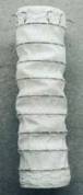
Figure 1. A reinforced graft for vascular application to replace or repair damaged arteries (25mm diameter).

The same technique can be employed in many of the body's conduits, including the oesophageus, trachea, biliary system and urinary system. The technology of self-expansion or balloon-assisted expansion is used for many millions of these stents each year and the numbers are steadily increasing.

Introducing a catheter directly through the complex arterial channels via a small external incision is generally not possible, owing to the relative rigidity and lack of steerability of the catheter alone. To ensure that the catheter gets to the correct site, a guide-wire must first be introduced. Superelastic Ni-Ti alloys are used very successfully for this application. Their torquability, deformability, recovery and low whipping effect allow the surgeon to get the highly flexible guide wire in place. The end of the guide wire is fed through a central or side hole in the catheter. The catheter can only go where the guide wire is positioned - it acts like a railway line. Often, the guide wire may be kept in place while other catheters for different tasks use the same guide wire.

Vena-cava Filters

Vena-cava filters have a relatively long record of successful in-vivo application. The filters are constructed from Ni-Ti wires and are used in one of the outer heart chambers to trap blood clots, which might be the cause of a fatality if allowed to travel freely around the blood circulation system. The specially designed filters trap these small clots, preventing them from entering the pulmonary system and causing a pulmonary embolism. The vena-cava filter is introduced in a compact cylindrical form about 2.0-2.5mm in diameter. When released it forms an umbrella shape. The construction is designed with a wire mesh spacing sufficiently small to trap clots. This is an example of the use of superelastic properties, although there are also some thermally actuated vena cava filters on the market.

Dental and Orthodontic Applications

Another commercially important application is the use of superelastic and thermal shape recovery alloys for orthodontic applications. Archwires made of stainless steel have been employed as a corrective measure for misaligned teeth for many years. Owing to the limited “stretch” and tensile properties of these wires, considerable forces are applied to teeth, which can cause a great deal of discomfort. When the teeth succumb to the corrective forces applied, the stainless steel wire has to be re-tensioned. Visits may be needed to the orthodontist for re-tensioning every three to four weeks in the initial stages of treatment.

Superelastic wires are now used for these corrective measures. Owing to their elastic properties and extendibility, the level of discomfort can be reduced significantly as the SMA applies a continuous, gentle pressure over a longer period. Visits to the orthodontist are reduced to perhaps three or four per year.

This continuous, gentle, corrective force illustrates the rather odd elastic properties of superelastic SMAs. A graph showing extension plotted against load produces a straight, horizontal line after initial loading. This shows the alloy to be non-Hookean, unlike carbon steel and other springs and constant forces can be derived from springs made of Ni-Ti alloy.

Apart from the tensioned archwires, other superelastic orthodontic devices exist which can move teeth linearly where there is uneven tooth spacing. Movements of 6mm in 6 months are possible with minimum discomfort. Devices also exist that can apply torsional forces in the case of a “twisted” tooth. Orthodontists have modular kits, in which adhesively bonded brackets are attached to the teeth and the arch wire is then attached to and guided by the bracket. Other wire-forms can then be fitted to the brackets to push, pull, twist or force other movements that facilitate corrective measures for cosmetic or clinical reasons.

Such dental SMA devices have proved very successful in trials and are being made commercially available in Europe. Other similar SMA devices are also being used for healing broken bones - staples of the shape memory materials are attached to each part of the bone, and these staples then apply a constant, well-defined force to pull the two pieces together as the SMA is warmed by the body and tries to return to its original configuration. This force helps knit the two pieces of bone back together. Such smart ‘healing’ powers are the reason why SMAs are being borne in mind for many applications in the medical, dentistry and other fields in the future.